		Der ESP8266 und seine Weiterentwicklungen (ESP32, ...)
		könnten Schwergewichte im Internet der Dinge werden.

		Es ist eine 32-Bit-RISC-Prozessorfamilie mit den üblichen Schnittstellen
		und Funktionalitäten, die man von heutigen Microcontrollern erwartet.
		Eines der Highlights, das sowohl bei Profis als auch bei Hobbyisten
		Aufmerksamkeit auf sich zieht, ist das integrierte Wi-Fi (802.11 b/g/n).

		Die Prozessorfamilie besteht nur aus wenigen Basis-Chips,
		womit der chinesische Entwickler, Espressif aus Shanghai
		Skalierungseffekte bei der Fertigung optimiert.

		Das für Hobbyisten weniger geeignete SMD-Gehäuse wird durch die Vielzahl
		der am Markt angebotenen Module, zur Zeit (2019) schon mehr als ein Dutzend (ESP-01, ...),
		ihren unglaublich günstigen Preis, es gibt sie bereits ab ca. 3€ (ESP-01)
		und die Funktionsähnlichkeit innerhalb der Familienmitglieder, mehr als ausgeglichen.

		Bei manchen ist das WiFi schon an eine integrierte Antenne angeschlossen,
		bei anderen ist ein Anschluß für eine externe Antenne vorhanden.
		Speichergröße, Anzahl der nutzbaren IO-Pins oder gar eine Kamera
		sind weitere Unterscheidungsmerkmale der diversen Module.
		Eine aktive Community liefert Ideen, Anregungen und Informationen zum ESP8266.

		Ursprünglich gabs die gesamte Dokumentation nur auf Chinesisch.
		Auch jetzt sind fundierte Informationen teilweise noch schwer zu bekommen.

		Selbstbau-Projekte basieren daher oft auf "Trial and Error". werden aber durch
		Anbieter, die Entwicklungsplattformen und Zubehör anbieten unterstützt.

		In diesem Artikel beschreibe ich, wie leicht man, auch ohne Löten zu müssen,
		einen ESP8266 auf einem Steckbrett zum Laufen bekommt.
		Das ist dann die Grundlage für weitere Bastelprojekte.
		Viele bzw. fast alle ESP8266-Module werden vom Lieferanten mit der AT-Firmware "betankt".
		So kann das Modul über ein einfaches Terminalprogramm gesteuert werden.
		Viel mehr braucht man nicht, wenn man vor allem die Wi-Fi-Fähigkeiten
		in Kombination mit einem anderen Microcontroller nutzen möchte.
NodeLua

A more sophisticated option is available from NodeLua,
which offers open source firmware based on the Lua programming
language. NodeLua is still in development, but already contains
extensive capabilities. Other choices include Python, BASIC, and the
Arduino IDE, which is featured in this article.
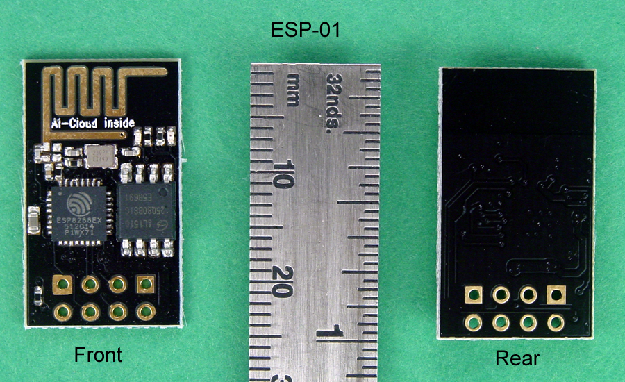
The ESP-01 module contains the ESP8266 MCU and a flash memory chip. There are two LED's: a red one which indicates power is connected to the module, and a blue one which indicates data flow, and can also be controlled by user programming. The Wi-Fi antenna is the PCB trace that covers the top of the module; it's called a Meandered Inverted-F Antenna (MIFA,) is surprisingly efficient, and only mildly directional.
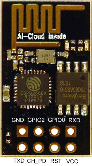
There are eight connection pads near the bottom of the module; the figure above identifies their functions. Usually, two 4-pin male headers are inserted in the rear of the module and soldered on the front. This makes the I/Os accessible, but is not breadboard friendly, and requires flywires from the ESP-01 to a solderless breadboard. This technique works, but it is messy. There is an alternative way as shown below.
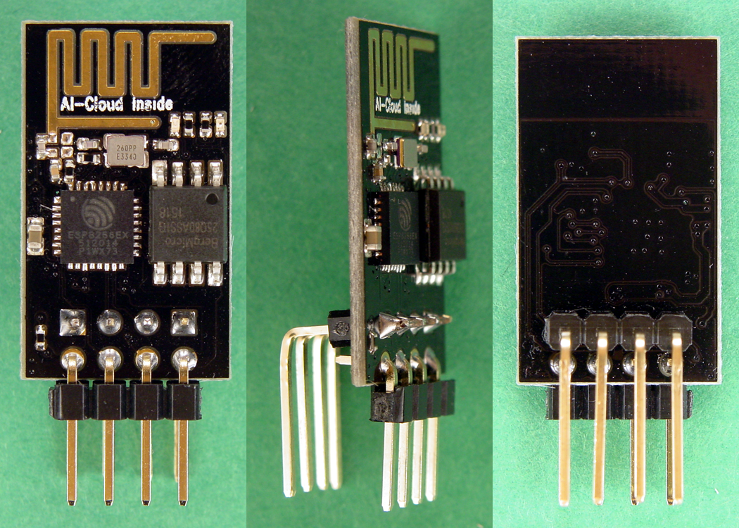
The header on the front of the PCB uses standard right angle pins with no modifications required. The header on the rear uses extra long pins that have been bent in a right angle configuration to accomplish .3" of separation between the rows. This method allows the ESP-01 to be inserted in a solderless breadboard in the vertical orientation straddling the center gap, and makes all eight pins independently accessible.
The schematic diagram below shows the connections required to the ESP-01, and the photographs show the completed solderless breadboard assembly. The wire colors on the schematic correspond to the wire colors in the photographs.
Construct the assembly as shown, but do not connect the cable from the USB to TTL converter to the PC until you have set the shunt on the converter PCB to the 3.3V position, and double checked all wiring. Using 5V to power the ESP-01 could damage it beyond repair.
Editor's note: A more reliable flashing circuit is available here, and should be used instead of the circuit described in this article.
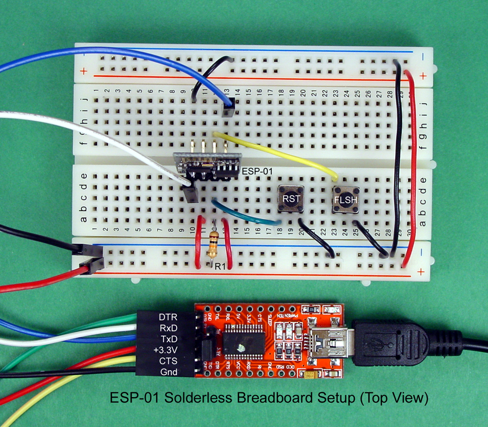
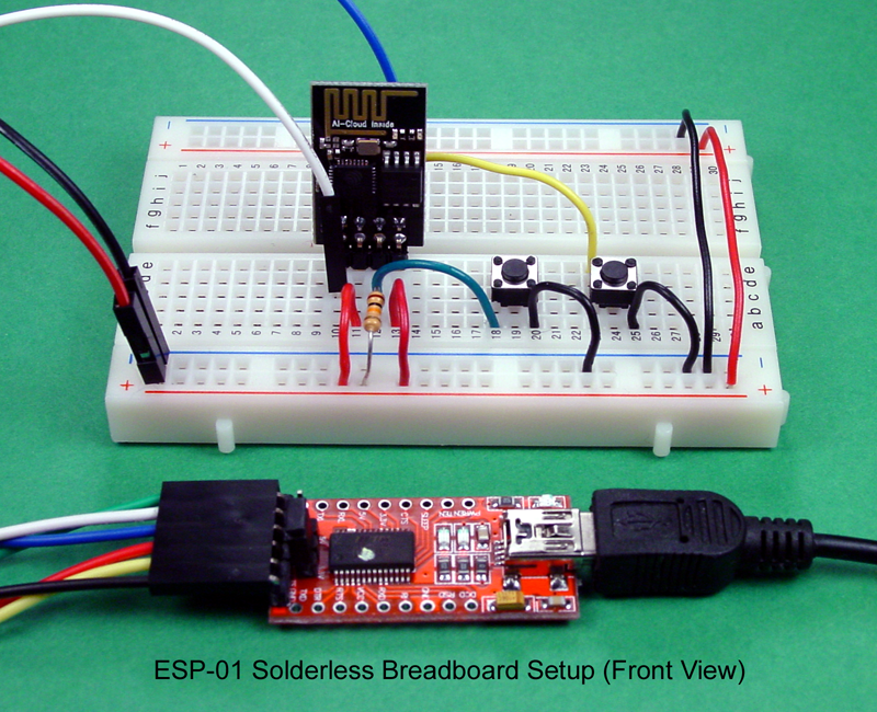
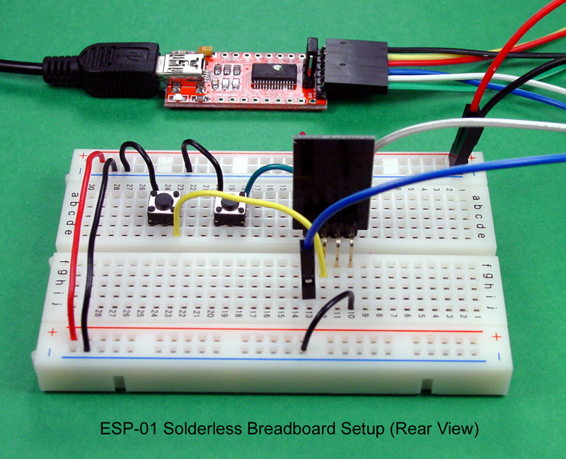
Between the schematic diagram and the photographs, you should have most of the information needed to assemble the solderless breadboard setup. The notes below will also help.
As you see in the photographs above, the use of fly wires from the USB to TTL converter is not optimum. A better option is to replace the six right angle pins on the converter with six straight pins on the bottom of the PCB. The modification will allow the USB to TTL converter to be plugged into the solderless breadboard and will result in a much neater and less fragile assembly, as shown in the following photo.
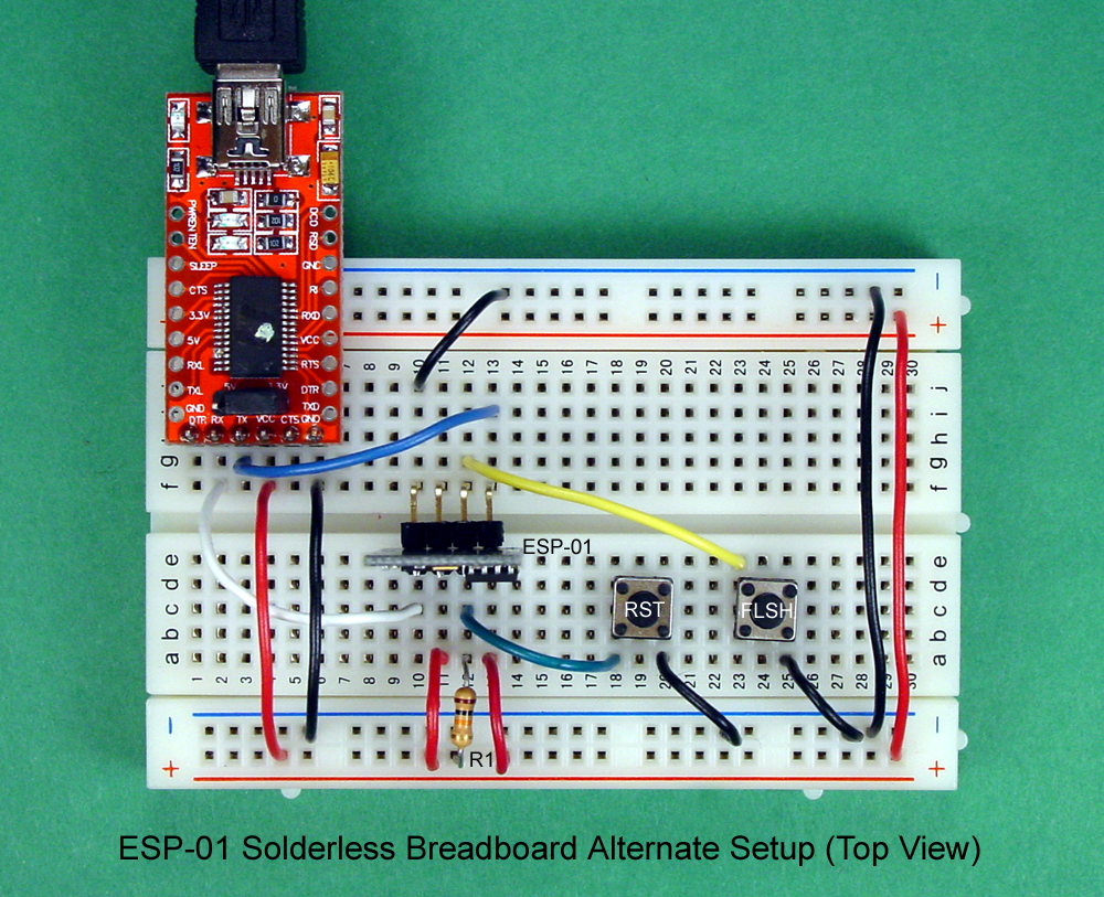
Before connecting the USB to TTL converter to your PC, check to be sure that the voltage selection shunt is in the 3.3V position, and that all the wiring on the ESP-01 breadboard setup is correct and secure. Then, plug the USB cable in; the red LED on the ESP-01 should light and stay on, and the blue LED should flicker whenever there is signalling between the EXP-01 and the PC. Next, test the reset switch by pressing and and holding it down. Look at the ESP-01; when you release the reset switch, the blue LED should flash twice. If all is well at this point, disconnect the circuit from the PC and proceed to the next section.
The recommended Arduino IDE version for use with the ESP8266 modules is Version 1.6.5. If you have an earlier version, you can try it and see if it works, or you can upgrade to 1.6.5.
Reconnect the circuit to the PC and confirm that the red LED on the ESP-01 is lit. Click Tools, Port, and select the port where the ESP-01 is connected. Finally, you are ready to program the ESP-01.
Press and hold the Reset button, and then press and hold the Flash button. Release the Reset button, and while holding the Flash button pressed, click the Upload arrow in the Arduino IDE. The sketch should compile in a minute or so, and when it is complete, release the Flash button. The compiled code will be sent to the ESP-01; as it is sent, the blue LED on ESP-01 will flicker.
To see the results of all this clicking and choosing, click Tools, Serial Monitor, and set the baud rate in the lower right corner of the Serial Monitor window to 115200. If you have an earlier version of the ESP-01 (probably built on a blue PCB,) the baud rate is most likely 9600.
The ESP-01 should be scanning for Wi-Fi networks and reporting the results in the Serial Monitor window, as shown in the example below.
You should see your own network in the report, and all other networks that are within range of the ESP-01. The numbers in parentheses show each network's signal strength, and because the numbers are negative, lower numbers represent stronger signals.
The ability to program an ESP8266 using the Arduino IDE hugely expands the user base for these Wi-Fi enabled chips. The ESP-01 and its larger cousins provide an extremely capable hardware platform at a low cost. Add the ease of use of the Arduino IDE, and designing applications for the internet of things is within the reach of almost anyone.